How-to: Wacker BPU2440 & BPU2950 Exciter Repair
Posted by David Schatz, Owner - DHS Equipment on Mar 30th 2017
The exciter on the Wacker BPU2440 and BPU2950 is the mechanism that creates the vibration in the plate compactor. Without a properly functioning exciter, your BPU2440 or BPU2950 will not do its job. We've compiled all the information you need to properly service the exciter.
Removing the exciter:
- Turn machine’s engine off
- Remove belt guard and remove drive belt
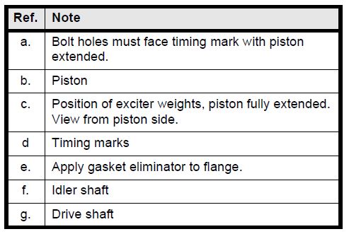
- Using a 3-jaw puller (a), remove pulley (b) from exciter drive shaft
- Clamp the control line hose with locking pliers or C-clamp to prevent leaking. Then, disconnect the line from the front exciter flange cover
- Using a 19 mm socket, remove the four hex nuts (c) that secure the tubular frame (d) to the plate. Remove the frame from the plate
- Using an appropriate lift or crane, lift the complete upper mass from the baseplate to expose the exciter assembly.
- Mark the exciter housing referencing the right hand front side (e).
- Remove the eight socket head screws (f) securing exciter and lift the exciter from the plate.
Installing the exciter:
- Scrape off old gasket material and thoroughly clean mounting surfaces on exciter and baseplate
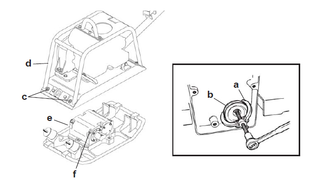
- Once thoroughly clean and completely dry, coat mounting baseplate (a) with Loctite 515 gasket eliminator or equivalent
- Position exciter assembly so that exciter drive pulley faces front right corner (b) of plate
- Coat threads of mounting bolts (c) with Loctite 242 or equivalent, contact us for torque specifications
- Inspect shockmounts (d). Replace any that appear worn or damaged
- Coat threads of shockmount with Loctite 242 or equivalent, contact us for torque specifications
- Position upper mass onto lower mass and secure with nuts. Contact us for torque specifications
- Install new tolerance ring (e) and carefully tap on exciter drive pulley (f) until it is flush against shaft shoulder
- Connect control hose and bleed the system
- Install drive belt. Adjust belt tension and check alignment of pulleys. Replace belt guard cover
- Fill exciter (g) with oil
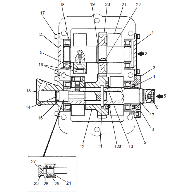
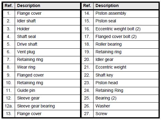
Exciter assembly cross section:
Disassembling the exciter:
- Mark front corner of housing on side that exciter pulley attaches to
- Jam the gears to prevent them from turning and remove all exciter weights (21)
- Remove snap rings (7, 10) from drive shaft
- Mark location of all flange covers (1, 2, 9, 13) and remove covers from exciter
- Note: Flange covers (9, 13) on drive shaft are equipped with threaded pusher holes (a)
- Remove drive shaft (2) Place exciter in an arbor press pulley side up. Press on pulley side of drive shaft (b) until the shaft is pushed completely through the side of the housing. The shaft will press out with sleeve gear (12), piston assembly (14), and inner bearing races intact
- Note: During this step the roller bearing on the opposite end of shaft will be pressed out of exciter housing. Remove bearing as it becomes free of housing to prevent it from falling
- Use arbor press or 2-jaw puller to remove bearing races and sleevegear bearing (12a)
- Remove piston assembly (15) from drive shaft by placing on a wooden V-block (c). The block should have a hole drilled in it for the guide pin (11). Press guide pin (d) (DO NOT HAMMER) through shaft until piston (e) can be removed. Spin head (23) of piston assembly by hand and check condition of small bearings (25) inside. Head should rotate smoothly with no side play. If necessary, remove retaining ring holding head and replace bearings
- Press idler shaft from exciter.
- Use an arbor press or puller to remove bearing race and idler gear (20)

Re-assembling the exciter:
When installing shafts, make sure drive shaft is installed on machined end of housing. Later housings are symmetrical and are machined at all four bearing locations. On these housings, the drive shaft may be installed on either side.
Installing idler shaft:
- Assemble retaining ring (19), key (22), gear (20), and bearing races onto shaft
- Press roller bearing into one side of exciter housing. Use a flange cover as a guide in positioning the bearing the correct distance into the housing
- Install the idler shaft. Complete the installation by pressing the remaining bearing into the opposite side of housing. Position the bearing into the housing using a flange cover
Installing drive shaft:
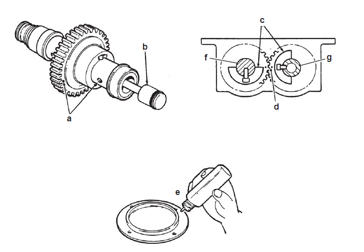
- Using the wooden V-block to secure shaft, position the piston assembly (14) in shaft and press guide pin (11) through. Caution: Do not hammer on guide pin. Hammering may mushroom top of pin and cause it to bind in the sleeve gear
- Note: When installing guide pin, make sure it extends an equal distance on each side of shaft so it will slide freely once sleeve gear is installed
- Press sleeve gear bearing (12a) on shaft and secure in place with retaining ring (10)
- Press bearing race on pulley side of shaft. Do not install bearing race on opposite side of shaft until shaft and sleeve gear are in place
- Insert drive shaft assembly through housing and slide sleeve gear (12) on shaft and over sleeve gear (12a)
- Note: Sleeve gear must be installed so that when the piston assembly is pulled out, the bolt holes in the shaft face the timing mark on the gear
- Press bearing into pulley side of exciter housing. Position it in the housing using a flanged cover

Timing the exciter weights:
- Align timing marks on gears with piston extended. View shafts from piston side and compare position of bolt holes in shafts and timing marks on gears with those shown. If bolt pattern does not match sleeve gear was installed incorrectly. Back gear off bearing and rotate it one half turn
- Install wear ring (17)
- After installation is complete, operate piston by hand and make sure both sleeve gear and piston slide freely. Using Loctite 515 gasket eliminator or equivalent on flange, assemble it to housing. Coat M10 screws with Loctite 242 or equivalent and secure flange to housing. Contact us for torque specifications
- Install retaining ring (7) on end of drive shaft
- Once assembled, exciter weights can cause exciter shafts to turn unexpectedly and with considerable force. Keep fingers and hands away from gears and weights when handling exciter assembly to prevent being pinched. Install exciter weights. Coat threads of M10x25 screws with Loctite 271 or equivalent and secure weights to drive shaft. Coat threads of M10x35 screws with Loctite 271 or equivalent and secure weights to idler shaft. Contact us for torque specifications
- Re-install the exciter assembly to plate